With the progress of technology and innovation of material, a newly material have been applied to many industries. That is zinc alloy material, which is used to process various shapes cast parts, with corrosion resistance, solid, strong strength, mechanical property and low cost. So many die casting manufacturer had chosen to produce zinc die casting components to meet the demand of clients and markets. However when designing zinc die casting part structure , there are key factors to consider. What is Zinc Die Casting Components Design Guide ? Hereby We suggest some solutions and attentions. That is 5 critical factors to consider when designing zinc die casting part structure.
Firstly, Wall Thickness is Considered
When our engineers design wall thickness of a die casting part, Considering that uneven or excessively thick walls can lead to negative issues such as shrinkage and wrapping, part bend and rough surface. If walls are too thin may cause structural defect or lead to incomplete filling during the casting process. So we must comply with the below a few crucial points.
Optimize Wall Thickness
We should maintain uniform wall thickness across the part to promote even cooling and minimize stress. When designing zinc die casting part , we recommand that its wall thickness range of 0.6mm to 2.5mm is generally ideal. The desired thickness depends on part size and application in detail.
Tapered Walls
In order to enhance the internal structure of the die casting part, Our engineers consider of a skilled designing of engineering and achitechture. It means gradually decrease or increase in thickness from one end to the other, creating a sloped or angled surface rather than a uniform vertical structure.
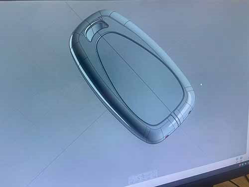
Simulations
Conduct flow and cooling simulations on the design software when designing a die casting component, and predict and resolve potential issues in operation. Avoid and prevent some operation issues from mass production. And save more man hours and the cost of prototyping in cast trial.
Secondly, Draft Angle is An Essential Factor
Draft angles are essential in casting die design. Insufficient or absent draft angles can lead to stuck parts, surface defects, even though damage to the mold. Draft angle should be designed rightly when designing precision casting die. How to set draft angle to fit the die and mold smooth works ? Please attend the following points.
Recommended Draft Angles
Our enigineer suggest that a draft angle of at least 1° to 3° for most surfaces. The deeper cavities or textured surfaces needs the larger angles. we should guarantee designing zinc die casting part quality is perfect, the draft angle design is properly and reasonable. And avoid damaging the surface of the cast part.
Thirdly, Ribbing and Reinforcement Features
When we design the structure of the part, added rib operation is essential assist for strengthening parts. Without significantly increasing their weight or excess material . Want to design the right ribs to reinforce zinc casting part structure and functionalities. The follow methods makes us having a perfect result.
- Choose The Appopriate Thickness Ratio: Design rib thickness at about 50-60% of the main wall thickness to minimize sink marks.
- Rounded Fillets or Radii Option
- Select The Right Positions And e;hance the internal structure of die cating part
Fourth, Tolerances and CNC Machining Allowances
Zinc die casting requests excellent dimensional accuracy. Sometimes we must consider that we may require secondary machining when they need accuracy dimensions. Precise cnc machining can process zinc casting parts until high tolerance is achieved. How to ensure that zinc casting parts machined reach tight tolerance dimension accurancy ? We suggest manufacturers to do the blew actions.
1. Common standard tolerances achievable with zinc die casting (e.g., ±0.025mm for critical dimensions and ±0.10mm for non-critical ones).
2. Conduct detailed tolerance stack-up analysis during design, And ensuring all dimensions meet functional and assembly requirements.
Fifth, Undercuts and Complex Geometries
Undercuts and complex geometries can enhance functionality, especially some complex geometries and specific functionality parts are designed. They often require additional tooling design, such as cores or slides, which increase cost and complexity. How to cast complex geometries ? several points as following Iisted.
1. Undercuts maybe increase some specific functionalities of the casting part, but the die should add the additional tooling functions .
2. Use slides or cores only where absolutely necessary to create complex features for specific functionalities parts.
Conclusion
Designing zinc die casting part stucture requires a balance between performance, manufacturability, and cost-effectiveness. By Focusing on critical factors such as wall thickness, draft angles, ribbing, tolerances, and complex geometries. We can create parts that meet functional requirements and practise. Implementing these best practices into your design process, along with advanced simulation tools and collaborating with experienced engineering teams. As one professional die casting manufacturer with a strong engineering design capability and great manufacturability, we will use our worthtrust service and deligent afforts to provide premium quality final products to our clients and business partners.


