Factors for zinc die casting part structure design should be considered when we want to finish complex zinc die casting project. Especially zinc alloy material, which is used to process various shapes cast parts, with corrosion resistance, solid, strong strength, mechanical property and low cost. So many die casting manufacturer had chosen to produce zinc die casting components to meet the demand of clients and markets. However when designing zinc die casting part structure , there are key factors to consider. What is zinc die casting part design guide ? Hereby We suggest some solutions and attentions.
Firstly, Wall Thickness, One Of Factors For Zinc Die Casting Part Structure Design
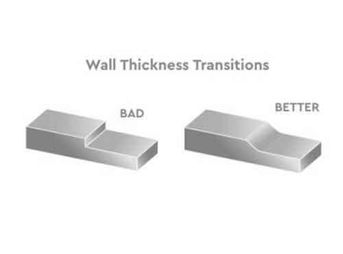
When our engineers design wall thickness of a die casting part, Considering that uneven or excessively thick walls can lead to negative issues such as shrinkage and wrapping, part bend and rough surface. If walls are too thin may cause structural defect or lead to incomplete filling during the casting process. So we must comply with the below a few crucial points.
- Optimize Wall Thickness: Maintain uniform wall thickness across the part to promote even cooling and minimize stress. Wall thickness range of 0.6mm to 2.5mm is generally ideal.
- Tapered Walls: Enhance the internal structure of the die casting part, decrease or increase in thickness from one end to the other, creating a sloped or angled surface rather than a uniform vertical structure.
- Simulations: Conduct flow and cooling simulations on the design software,predict and resolve potential issues in operation. This saves more man hours and the cost of prototyping in cast trial.
Secondly, Draft Angle is An Essential Factor
Draft angle is essential factor for zinc die casting part structure design. Insufficient or absent draft angles can lead to stuck parts, surface defects, even though damage to the mold. Draft angle should be designed rightly when designing precision casting die. How to set draft angle to fit the die and mold smooth works ? Please attend the following points.
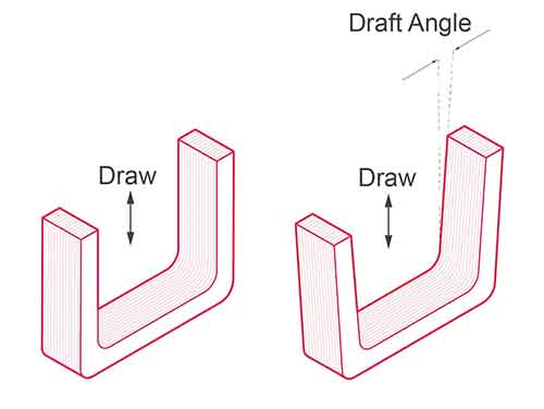
Draft Angles : Keep all vertical walls having a draft angle between 1° and 3°. This helps ejecting out of the part from the die, like some even wall thickness cast parts, which can eject out of the cavity of the die when the die opened. and avoid stick the die and stuck.
Thirdly, Ribs And Bosses Setting
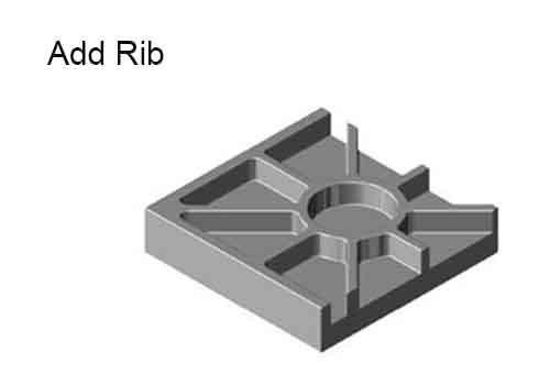
When we want to having a excellent zinc die casting part structure design, added rib operation is essential assist for strengthening parts. Without significantly increasing their weight or excess material . Want to design the right ribs to reinforce zinc casting part structure and functionalities. The follow methods makes us having a perfect result.
Ribs & Bosses: To reinforce the structural integrity of the part, add ribs without significantly increasing weight or material costs. Bosses designed is convenient to assemble and avoid thick sections that can cause shrinkage. Recommanded added rib
- Choose The Appopriate Thickness Ratio: Design rib thickness at about 50-60% of the main wall thickness to minimize sink marks.
- Rounded Fillets or Radii Option.
- Select The Right Positions And e;hance the internal structure of die cating part.
Fourth, Undercuts and Complex Geometries
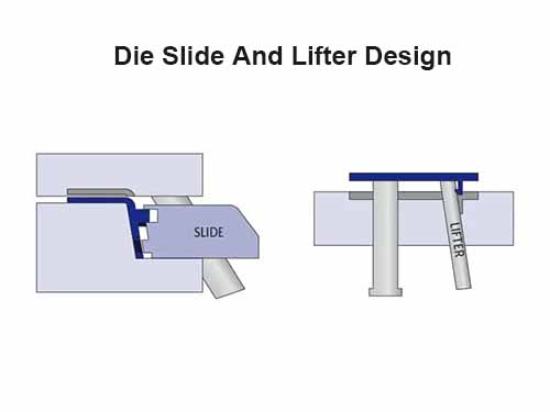
Undercuts: Die Slide And Lifter Design can be used but add cost if possible. But the fuction can resolve the design of intricate structure and functionalities of the cast part. Engineers use pillars to create more holes in the cast part, and to realize more functionalities. Undercuts makes casting die more complex, but can cast more functional cast parts.
Undercuts and complex geometries can enhance functionality, especially some complex geometries and specific functionality parts are designed. They often require additional tooling design, such as cores or slides, which increase cost and complexity. How to cast complex geometries ? when we need consdering having a good zinc die casting part structure design, several points as following Iisted is attended.
Undercuts and complex geometries can enhance functionality, especially some complex geometries and specific functionality parts are designed. They often require additional tooling design, such as cores or slides, which increase cost and complexity.
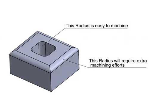
Fifth, Fillet Radii
Rounded internal or external corners are critical for improving metal flow, strength, tool life, and surface quality. As professional zinc die casting manufacturer, optimizing radii can directly reduce porosity, cracking, and premature die wear.
Recommended Internal Radius, Compare to The Wall Thickness
| Wall Thickness | Internal Radius |
|---|---|
| ≤ 1.0 mm | 0.25 – 0.4 mm |
| 1 – 2 mm | 0.5 – 1.0 mm |
| 2 – 4 mm | 1.0 – 1.5 mm |
| >4 mm | ≥ 1.5 mm |
External Radius
- Equal to internal radius + wall thickness
- Slightly larger for strength and aesthetics
Sixth, Surface Finish & Textures
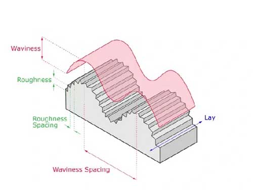
Surface Finish & Textures: Polished the die and achieve smoother finishes, texture treatment needs some precision process equipment to process. Engraved textures can mark the constract texture on it when the cast part is made.
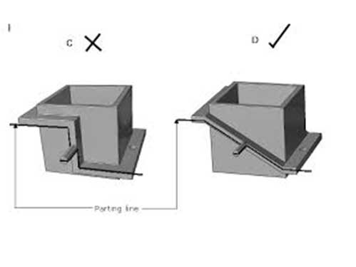
Seventh, Parting Line & Ejection
Parting Line & Ejection: Parting Line Location: keep consistent optimization of the cavity and the core of the die , and reduce the creak between the halves of the die, minimize flash & finishing work. Ejection Pins: Put the ejector pins on the non-critical areas, to avoid visible marks on critical surfaces, ensure high quality cast part.
- Common standard tolerances achievable with zinc die casting (e.g., ±0.025mm for critical dimensions and ±0.10mm for non-critical ones).
- Conduct detailed tolerance stack-up analysis during design, And ensuring all dimensions meet functional and assembly requirements.
Eighth, Tolerances and CNC Machining Allowances
Zinc die casting requests excellent dimensional accuracy. Sometimes we must consider that we may consider of secondary machining when they need accuracy dimensions. Focus on having a proper zinc die casting part structure design so that precise cnc machining can process zinc cast parts until high tolerance is achieved. How to ensure that zinc cast parts machined reach tight tolerance dimension accurancy ? Precision die casting part CNC machining achive the target.
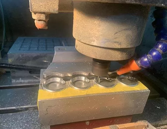
CNC machining have become indispensable process after die casting parts are made. Some die casting parts request having an accurate dimensions and high precision tolerance. So we should adopt some cnc machining equipment to process these parts in further.
- CNC Machining Improves Imperfection Defects On Die Casting Parts
- CNC Machining Enhances Features of Die Castng Parts
- Positioning dimension and removing the sharp edges and execess parts on the casting parts
- Increasing Production Effection And Ensure High Quality Products

Die Casting Project Quote
Find one of professional die casting factory to finish your project? If you want, please contact us by Email here !
Conclusion
8 factors for zinc die casting part structure design involves of the part’s performance, manufacturability, and cost-effectiveness. By Focusing on critical factors such as wall thickness, draft angles, ribbing, tolerances, and complex geometries. We can create parts that meet functional requirements and practise. Implementing best practices into your design process, along with advanced simulation tools and collaborating with experienced engineering teams. As one professional die casting manufacturer with a strong engineering design capability and great manufacturability, How can a manufacturer process high quality zinc die casting products? Die casting design is fatal vital.